Sine Wave Inverter Circuit Diagram With Code
Hp 8720b pdf user manuals.
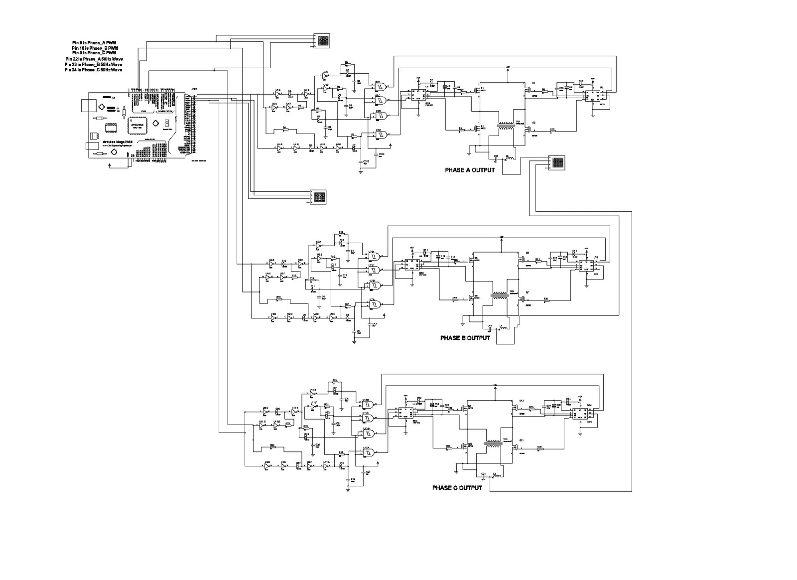
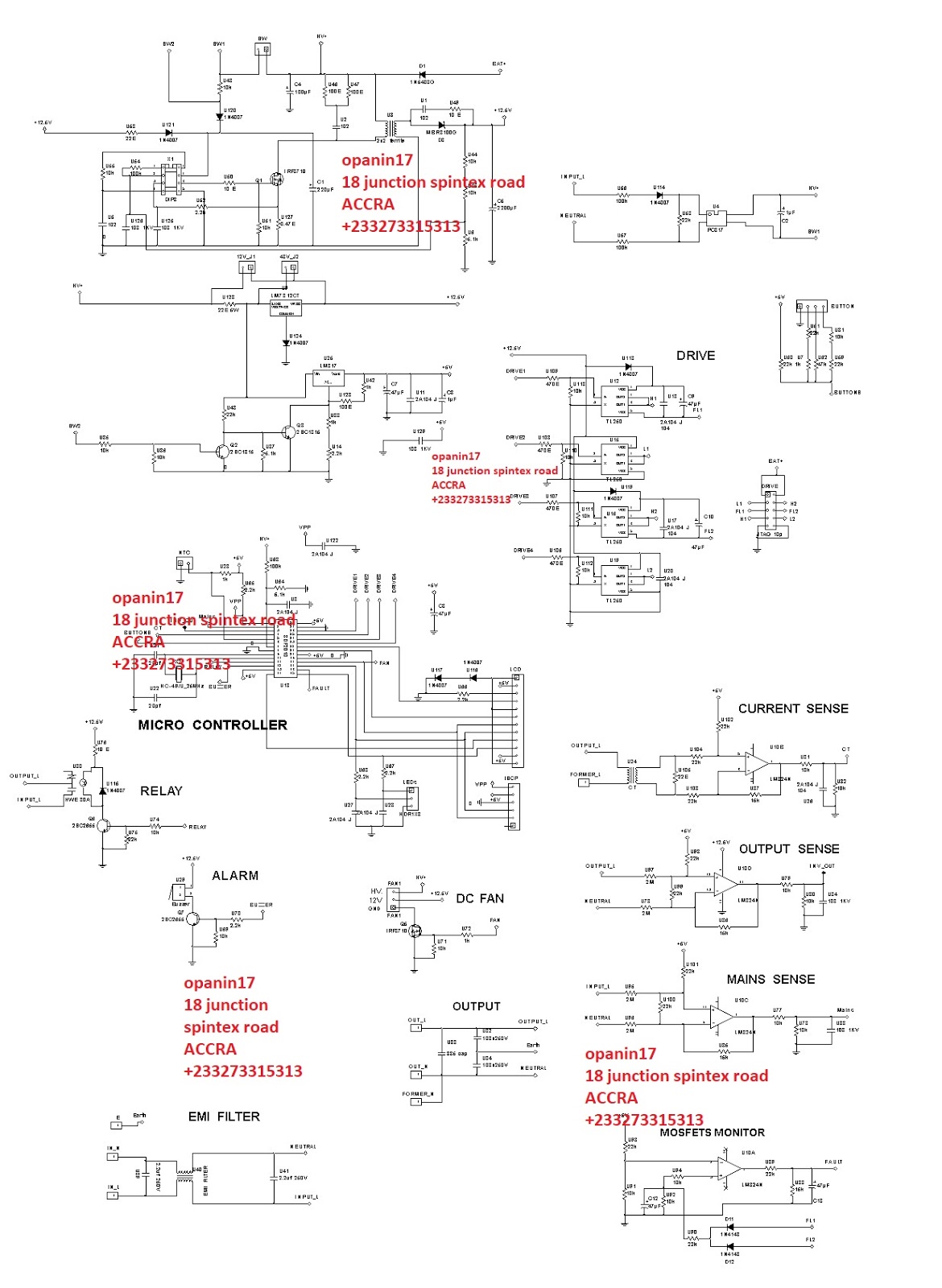
Sine wave inverter circuit diagram with code. In this post we are going to construct a circuit using arduino which can generate 3 phase sine wave with 120 degree phase difference whose frequency can be varied by using a potentiometer. 100 watt inverter circuit diagram parts list design tips. Inverters are devices that convert dc input supply to ac alternating current. They are also called power inverters.
Here you will find our home made pure sine wave power inverter based on spwm eg8010. It converts 48v to 220v with 3000 watts output. The post discuses the how to make a 3 phase inverter circuit which can be used in conjunction with any ordinary single phase square wave inverter circuit. Working of dc to ac inverter.
This is a simple inverter circuit based on 555 timer ic. Here timer ic wired as an astable multivibrator mode. We have already discussed about astable multivibrator using 555. Using the sg3525 pwm controller explanation and example.
Circuit diagram schematic of push pull converter. With ni multisim and ni labview software you can implement desktop simulation of your entire analog and digital system before prototyping. This tutorial shows you how to use the m.


