Pure Sine Wave Inverter Circuit Diagram Pcb
Assemble the circuit on a pcb as it saves time and minimises assembly errors.
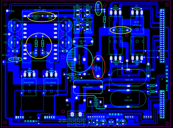
Pure sine wave inverter circuit diagram pcb. This feature is not available right now. Please try again later. Pure sine wave inverter with led and lcd the inverter pcb is easy to assemble by following the label of the components to be inserted. The choice of the voltage to be used to power the inverter ranging from 12v to 96v depends on kva you are designing.
For any setup a 12v relay is to be use. In the above section we learned the basic version of ic sg3525 designed to produce a modified sine wave output when used in an inverter topology and this basic design cannot be enhanced to produce a pure sinewave waveform in its typical format. 600w pure sine wave power inverter circuit principle. The inverter is divided into four parts each part make a pcb board.
They are power board spwm driver board dc dc driver board and protection board. Thanks for sharing a good schematic of pure sine wave inverter i want to build this inverter and require following information. Where we connect j1 and j2. Of the thousands of images on the internet related to images of sine wave inverter circuit diagram 2019 weve picked out the best for you including sine wave inverter circuit diagram pure using ic 555 schematics world sine wave inverter circuit diagram adaptable 12vdc 220vac pure sinewave sine wave inverter circuit diagram 1kva 1000 watts pure projects to try sine wave inverter circuit.
Pure sine wave inverter circuit diagram working. In last article on spwm generation i have discussed how to implement sinusoidal pulse width moudulation using microcontroller and how to select number of pulses and duty cycle of each pulse. An actual size single side pcb for the sine wave inverter circuit is shown in fig. 2 and its component layout in fig.
Suitable connector con1 is provided on the pcb to connect the mosfet banks and the transformer externally. Connector con1 pins a through f are also marked on schematic.


