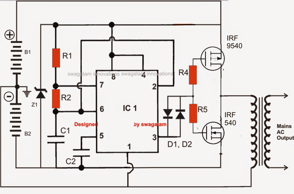
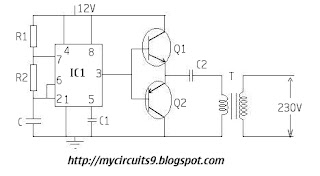
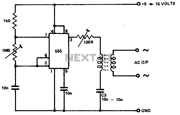
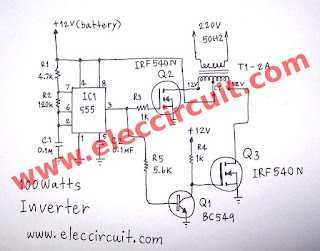
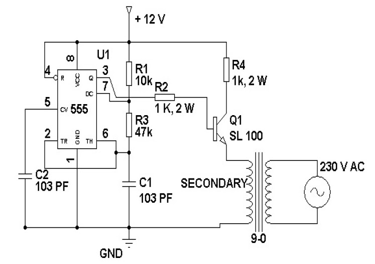
Ne555 Inverter Circuit
The circuit inside the 555 is just an amplifier with 2 inputs and an output.
Ne555 inverter circuit. Clap switch circuit using ne555 timer ic gallery of electronic circuits and projects providing lot of diy circuit diagrams robotics microcontroller projects electronic development tools. The 555 timer ic is an integrated circuit chip used in a variety of timer pulse generation and oscillator applications. The 555 can be used to provide time delays as an oscillator and as a flip flop element. This sg3525 inverter circuit is suitable for 100 watt applications.
This article contains circuit diagram ic features working and video demonstration of the circuit. Block diagram of automatic plant irrigation system. Circuit is not that much complicated. We use the basic concept in this circuit ie.
Soil have high resistance when it is dry and has very low resistance when it is wet. Circuiti schemi elettronici soluzioni e applicazioni dogni genere. 100watt inverter circuit inverter circuits are among the easiest circuits to build for newbies. Here is the circuit diagram of a simple 100 watt inverter using ic cd4047 and mosfet irf540.
Crystal controlled oscillator circuit. This general purpose signal source serves very well in signal tracing applications. The output level is variable to more than 1 v rms into a 50w load. What is the 555.
The 555 is an 8 pin chip that can be turned into lots of different things building blocks.


