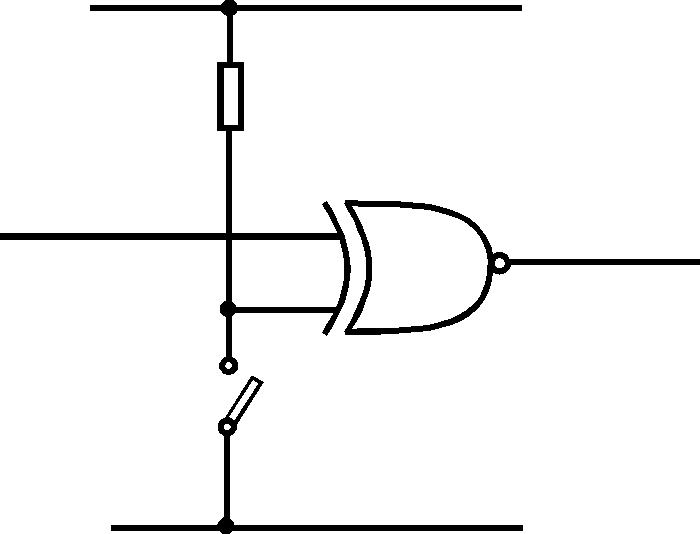
Inverter Logic Gate Circuit
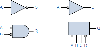
Inverters simply output the opposite as the input.
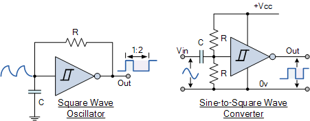
Inverter logic gate circuit. An inverter circuit outputs a voltage representing the opposite logic level to its input. Its main function is to invert the input signal applied. Integrated circuits ics logic gates and inverters are in stock at digikey. Integrated circuits ics ship same day.
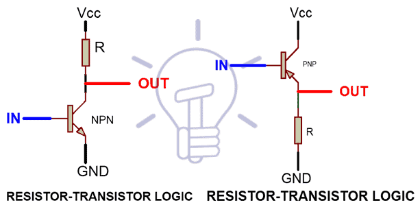
An inverter or logic not gate can also be made using standard nand and nor gates by connecting together all their inputs to a common input signal for example. A very simple inverter can also be made using just a single stage transistor switching circuit as shown. Bipolar logic and interfacing. This feature is not available right now.
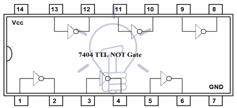
Please try again later. A not gate often called an inverter is a nice digital logic gate to start with because it has only a single input with simple behavior. A not gate performs logical negation on its input. In other words if the input is true then the output will be false.
A variety of digital logic circuit techniques have been in use since the 1960s when integrated logic gates were first produced. In this lab activity the transistor transistor logic ttl circuit inverter not gate and 2 input nand gate configurations are examined. The single transistor inverter circuit illustrated earlier is actually too crude to be of practical use as a gate. Real inverter circuits contain more than one transistor to maximize voltage gain so as to ensure that the final output transistor is either in full cutoff or full saturation and.
A not gate is often referred to an inverter.


